
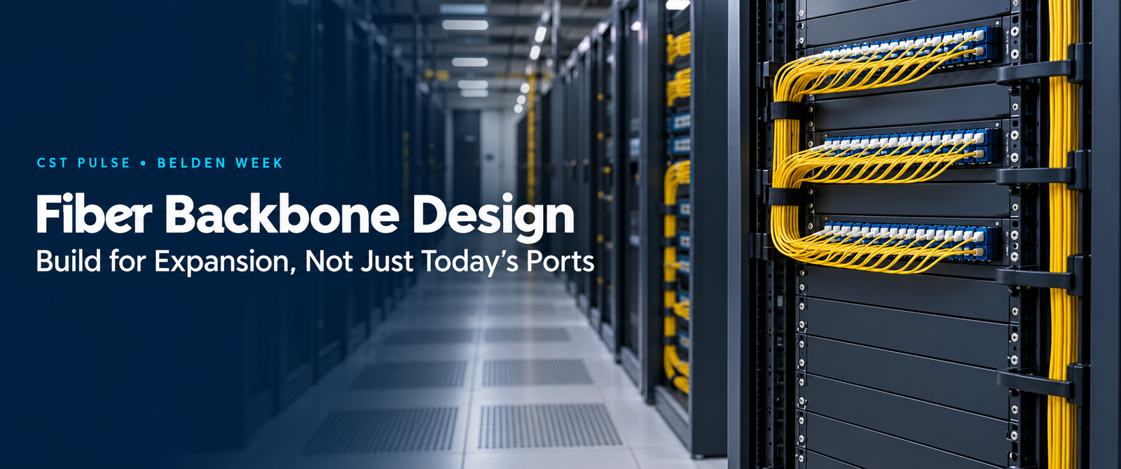
Fiber backbone design should account for the network’s next stage, as well as its current connections. A new building, additional equipment room or higher-speed uplink can change the demands on infrastructure that an organization expects to retain for years.
However, many specifications still begin and end with “24-core fiber” or “48-core fiber.”
Those descriptions establish a fiber count. They do not establish the fiber type, route, optical performance, termination method or expansion strategy.
For enterprise SIs and consultants across Africa, the practical question is therefore broader: how will this backbone accommodate growth without making every change a disruptive construction project?
Start fiber backbone design with the application and architecture
First, map the buildings, equipment rooms, racks and services that the backbone must connect. Record actual cable routes and distances, including vertical runs and service allowances.
Next, identify current applications and credible expansion scenarios. For example, a university may add teaching blocks, while a hospital may expand diagnostic services or a data center may introduce another row of racks.
These changes do not necessarily require the same architecture.
A campus may use a hierarchical star with links to building distributors. Meanwhile, a data center may need structured connections between equipment zones that support its chosen network topology.
Therefore, show the distribution points and cross-connects on the design. Also identify which links carry critical services and where an outage would affect several downstream areas.
The design should explain where connections go, how technicians will manage them and where future capacity can enter the system.
Fiber backbone design: choose the right fiber type
Single-mode and multimode selection should follow the application, distance and optical interface.
OS2 single-mode is a strong candidate for campus links, longer routes and designs that need flexibility across future optical applications.
OM4 multimode can suit shorter links within buildings or data centers when the selected optics support the required distance and performance.
However, neither label guarantees that every future speed will work over the proposed channel. Check the specific transceiver application, fiber category, reach and connection-loss limits. Belden’s guidance similarly distinguishes fiber choices by application and distance.
Furthermore, compare the complete installed solution. Include optics, termination, testing, maintenance and future conversion costs instead of comparing cable prices alone.
The cable construction also matters. For example, outdoor ducts, exposed routes and indoor risers create different requirements for water protection, mechanical strength and fire performance.
Therefore, specify a cable that suits the route and applicable project requirements—not simply the required glass type.
Calculate core count from a fiber allocation schedule
A useful fiber backbone design assigns capacity to named requirements.
Start with working links. Then add planned services, migration allowances and an operational reserve that reflects the site’s expansion strategy.
For example, consider a route that currently needs six conventional duplex links:
| Allocation | Illustrative requirement |
|---|---|
| Six working duplex links | 12 fibers |
| Four planned additional duplex links | 8 fibers |
| Operational reserve | 4 fibers |
| Total | 24 fibers |
This example assumes two fibers per link. Other optical applications can use different fiber counts, so the actual interfaces must drive the calculation.
Moreover, the four reserve fibers do not create route redundancy. A cable cut can remove the working and spare fibers together.
If the organisation requires an independent second route, calculate its capacity separately. Also confirm that the surviving route can support the required services during a failure.
Consequently, “24-core” may describe a reasonable outcome for this example, but it is not a universal recommendation.
Spare capacity supports growth. Physical diversity addresses a different requirement.
Design physical diversity separately from spare capacity
Redundancy requires a review of shared failure points.
Two cables can follow different paths inside a building yet converge in the same external duct. Similarly, separate backbone links may enter through one vulnerable chamber or terminate in the same exposed location.
Therefore, trace both routes from end to end. Examine entrances, risers, chambers, equipment rooms and termination points.
A ring-shaped cable route alone also does not guarantee service continuity. The network design must provide suitable equipment, capacity and failover behaviour.
For critical services, document the failure scenarios that the design addresses. This makes the resilience discussion more useful than a simple “redundant fiber” line in the bill of quantities.
Plan LC and MPO connectivity as part of fiber backbone design
LC duplex connectivity provides individual duplex connections for compatible optical interfaces. It can offer straightforward patching where technicians manage services link by link.
By comparison, MPO connectivity groups multiple fibers into one connector. Designers can use it for pre-terminated trunks, cassette-based distribution or compatible parallel-optics applications.
MTP is US Conec’s brand of MPO connector; it is not a separate fiber category.
However, an MPO-based installation still needs a complete connection plan. Specify the fiber count, polarity, pinned or unpinned interfaces, connector polish and compatible cassettes or harnesses.
Also distinguish the trunk arrangement from the equipment interface. An MPO trunk may feed LC presentation through cassettes, while another application may require a direct multi-fiber connection.
As a result, a higher-speed migration might require different cassettes, patch cords or fiber allocations. It does not automatically mean replacing every component—or retaining every component.
Document the intended migration path before ordering the initial system.
Plan the optical loss budget in fiber backbone design
Every connector, splice and length of fiber contributes to channel loss.
Therefore, additional patching flexibility must fit within the selected application’s optical limits. More cross-connects may improve administration, but they also introduce additional connections.
Calculate channel loss using the specified component limits and route length. Then compare it with the application’s allowed channel insertion loss, while also checking reach and other relevant optical requirements.
Do not treat the full transceiver power budget as an allowance for cable and connector loss. Belden’s guidance explains that transmission penalties consume part of that budget.
Furthermore, assess the intended future application separately. A channel that supports today’s optics may not satisfy the loss or distance limits of the next interface.
Consequently, fiber backbone design should include both the initial channel calculation and an assessment of the proposed migration.
Balance density with maintenance access
High density can conserve rack space. However, the installation must remain serviceable after technicians populate it.
Check whether the layout gives technicians room to inspect connectors, operate cleaning tools and remove individual patch cords. Also verify that trays can move without pulling adjacent live connections.
In addition, plan bend-radius control, strain relief and slack storage. Allocate space for cable managers instead of treating every available rack unit as connection capacity.
Rack utilisation also involves depth, cable entry and working clearance. Therefore, review the populated rack arrangement—not just the number of ports on a panel.
For an enterprise LAN example, Belden’s FiberExpress ECX offers front- and rear-removable cassettes across its 1U, 2U and 4U housings. Its splice cassettes also incorporate slack management. These features illustrate how hardware design can support access during moves, adds and changes.
Useful density combines connection capacity with practical access.
Modular fiber backbone design for easier expansion
A modular system can let the installation grow in stages.
For example, a project may reserve housing capacity while initially installing only the required connection modules. However, the design must also reserve pathway space, cable-entry capacity and patch-cord management.
Belden’s DCX provides a relevant high-density example. Its official documentation describes modular cassettes and frames, several termination approaches, and cassette changes between Base-24, Base-12 and Base-8 arrangements without changing the housings. Its ODF housings also provide front access and cable-management features.
These options can support a staged deployment. Nevertheless, housing compatibility alone does not prove that an existing trunk will support a new optical application.
Check the complete path, including fiber mapping, connectors, polarity and loss. Then confirm the specific components required for the proposed migration.
Make moves, adds and changes part of the handover
Future expansion depends on accurate records as much as spare hardware.
Label the cable, distribution point, panel, port and fiber consistently. In addition, record which fibers serve working links, which support planned services and which remain available.
Before acceptance, inspect connector end faces, clean where necessary and re-inspect before connection. Verify continuity, polarity, length and insertion loss against the agreed test plan.
Where the specification requires OTDR testing, retain the traces alongside the other acceptance results. Also document the test methods and reference conditions so future technicians can interpret the records.
Finally, hand over route drawings, splice schedules, patching records and the expansion plan together. Otherwise, the next engineer may have spare fibers but no reliable way to identify or use them.
What a complete fiber backbone design should contain
Before requesting prices, bring the following into one coordinated design:
- Current applications, target interfaces and link distances.
- Fiber category and cable construction.
- Backbone topology and distribution locations.
- Working, planned and reserve fiber allocations.
- Physical route diversity and shared-risk locations.
- Connector types, polarity and termination methods.
- Channel-loss calculations and acceptance criteria.
- Housing capacity, rack space and maintenance access.
- Pathway allowances and staged expansion requirements.
- Labelling, test records and migration documentation.
Consequently, suppliers can quote against an engineering requirement instead of filling gaps with assumptions.
A 48-core cable may offer plenty of unused fibers. However, those fibers cannot compensate for an unsuitable optical channel, inaccessible patching or a single vulnerable route.
The core count describes the cable. The design determines how effectively the network can grow.
Share your routes, distances, current links and expansion plans with Core Solutions & Technologies. CST can help develop an appropriate Belden passive fiber infrastructure approach for your project.
Sources:
- Belden — Single-mode vs. Multimode Fiber: The Real Differences
Background on fiber selection, applications and distance. - US Conec — MTP PRO Connectors
Manufacturer reference identifying MTP as a brand within the MPO connector family. - Belden — Why You Should Know Your Link Model & Power Budget
Explanation of channel insertion loss and optical power budgets. - Belden — FiberExpress ECX Fiber Patch Panel System
Product reference for cassette accessibility and slack management. - Belden — DCX ODF Cassettes & Frames
Product reference for modularity, termination options and cassette migration. - Belden — DCX ODF Housings
Product reference for front access, cable management and housing configurations.
About CST Pulse
CST Pulse is the technology insight platform of Core Solutions & Technologies, covering practical ICT and ELV topics for system integrators and technology partners across Middle East & Africa.
Bring your next project to the table.
Talk to CST about this technology or application.